


 English
Add:No.45 Qianjia Industrial Zone,Yaoguan Town,Wujin District,Changzhou,China.
Zip:213011
Tel:+86 519 88770103
Fax:+86 519 88770103
Skype: calla_1985
Website: www.suncormotor.com
Email: info@suncormotor.com
Power Step 2H806M

Changzhou Suncor Motor Co., Ltd
Add.No.45 Qianjia Industrial Zone,Yaoguan Town,Wujin District,Changzhou,China.Zip:213011
Tel:+86 519 88770103
Fax:+86 519 88770103
Skype: calla_1985
Website: www.suncormotor.com
Email: info@suncormotor.com ; victor@suncormotor.com
facebooktwitterlinkedin google+
Key Features:
AC50-80V(DC70-110V) Supply Voltage
H-Bridge, 2 Phase Bi-polar Micro-stepping Drive
Suitable for 2-phase, 4, 6 and 8 leads step motors
Output current selectable from 1.8~7.8A peak
Current reduction by 50% automatically, when motor standstill mode is enabled
Pulse Input frequency up to 200 kH
Optically isolated differential TTL inputs for Pulse, Direction and Enable signal inputs8
Selectable resolutions up to 12800 steps
Over Voltage, Coil to Coil and Coil to Ground short circuit protection.
Introduction
2H806M is a cost effective, high performance bi-polar two phase micro-stepping drive applying pure-sinusoidal current control technique. It is best suited for the applications that desired extreme low noise and heat. It operates well in an environment, where electricity supply experience instability and fluctuation.
The general pseudo-sinusoidal current control technology adopted by majority of the drive produced distorted sine wave, and current ripple, resulting in vibration, noise and motor heating. This results in motor degrading over time, reducing in motor performance and shortens the usage life.
With an automatic optimization speed control technique, the PowerStep series drive output is very stable, with almost zero vibration and noise, performing close to a servo system, allowing the motor to operate smoothly. That helps to fulfill a design requirement of low noise, low heat and high performance.
Specifications
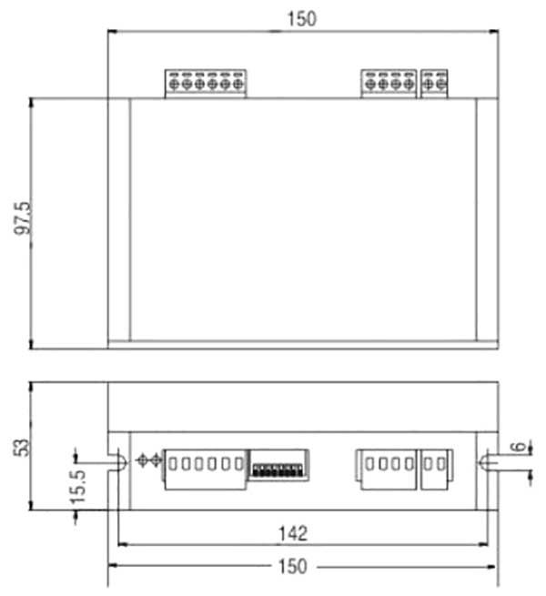
Dimensions
Dimensions in mm
Current Setting
Microstep Setting
* SW4: ON=Full current, SW4 : OFF=Half current
P1 Pin Assignment
P2 Pin Assignment
Wiring
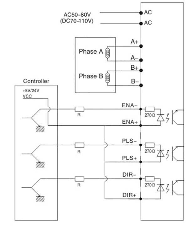
R=0 if VCC=5V
R=1K(Power>0.125W) if VCC=12V;
R=2K(Power>0.125W) if VCC=24V;
R must be connected to control signal terminal.
Message